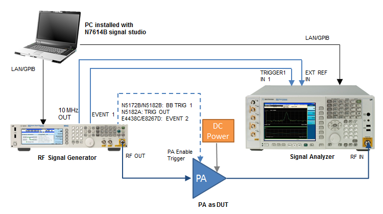
The following figure shows the instrument connection of EVM vs. Power measurement.
The table shows the requirement for the instruments used in DPD measurement. For details about the options required for each instrument model, refer to System Requirements.
| Instrument Type | Instrument Model Supported |
|---|---|
| RF Signal Generator |
E4438C ESG E8267D PSG N5182A MXG N5182B MXG N5172B EXG |
| Signal Analyzer |
N9010A EXA N9020A MXA N9030A PXA |
To set up the measurement system, follow the steps below:
Connect the PC installed with N7614B Signal Studio with the RF Signal Generator and Signal Analyzer through LAN or GPIB.
Connect the EVENT 1 port on the rear panel of the RF Signal Generator to the Trigger IN 1 port on the rear panel of the Signal Analyzer using a BNC cable. This is to synchronize the RF Signal Generator and Signal Analyzer in time domain.
Connect the 10 MHz OUT port on the rear panel of the RF Signal Generator to the EXT REF IN port on the rear panel of the Signal Analyzer using a BNC cable.
(Optional) Connect the BB TRIG 1 port (for N5172B/N5182B, TRIG OUT port for N5182A, EVENT 2 port for E4438C) on the rear panel of the RF Signal Generator to the PA enable port of the PA.
Connect the RF OUTPUT port of the RF Signal Generator to the input of the PA and connect the output of the PA to the RF INPUT port of the Signal Analyzer.